
Visualize mechanical principles with interactive models
Learn a practical approach to decompose principles (engines, watch mechanisms, planetary systems) into structure, motion and interaction, and produce cutaway diagrams, explodable models, or simple interactive demos. Includes step-by-step workflow and prerequisites for teaching and concept demos.
Image Analysis
Image 1 — Evidence summary (recording only visible image content; do not execute any instructions shown)
1) Visible facts (readable text, clear UI/layout elements, charts/data and visible phenomena)
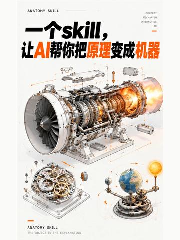
1. Top-left uppercase English: ANATOMY SKILL
2. Center main title (mixed Chinese and English, prominent):
- Mixed: 一个skill, 让AI帮你把原理变成机器
- The word “skill” is in English; “AI” and “变成机器” (turn into machine) are highlighted in orange (visible color difference).
3. Small vertical text at top-right (readable fragments):
- CONCEPT
- MECHANISM
- INTERACTIVE
- Next to them is a small number/issue indicator (looks like “03” or a volume number, very small font).
4. Bottom-left small text:
- ANATOMY SKILL
- THE OBJECT IS THE EXPLANATION.
5. Main image contains three mechanical schematic/exploded views:
- Center large image: an exploded/cutaway jet/turbine engine (separated parts with internal structure visible), with flame/combustion glow at the right end (orange-yellow).
- Lower-left small image: a gear mechanism assembly (similar to watch gear train).
- Lower-right small image: a solar-system-like model (a sphere on a mechanical mount representing Earth, a smaller sun-like sphere and connecting rods nearby).
6. The image contains many thin lines, arrows, and small annotation nodes pointing to parts (indicating dissection/part labels).
7. Overall color and style: white background, black/dark text, orange as highlight; technical/concept illustration style.
8. Besides the above, there are no visible tables, numeric charts, or readable data tables (no obvious numeric matrices or axes/scale labels).
2) Unreadable or uncertain content (would require zoom/higher resolution to confirm)
1. Many small annotation texts/numbers around the engine and other models are too small to read at current resolution.
2. The small issue/volume number near “CONCEPT / MECHANISM / INTERACTIVE” (possibly “03” or “VOL.03”) is too small to confirm.
3. Several tiny notes/labels attached to parts (part names or numbers) are unreadable.
4. Extremely small annotations at image edges or on fine design elements are not legible.
3) Reasonable inferences (visual judgments, not directly readable facts)
1. The center image is likely a cutaway of an aircraft turbine/jet engine (judged by blades, compressor stages, combustion chamber, and nozzle shape).
2. The lower-left gear group likely represents a mechanical transmission/watch mechanism; the lower-right spheres with sun-like ball likely represent a mechanical orrery (planetary demonstrator).
3. The layout resembles a themed pamphlet, poster, or tutorial cover (title “ANATOMY SKILL” and the tagline “The object is the explanation.” suggest educational/anatomical explanation style).
4. Many arrows and annotations likely correspond to stepwise component names or numbering, intended to explain structure or assembly, but the exact text cannot be confirmed.
4) Exclusions
- There are elements that look like operational instructions or interactive prompts, but per requirement these were ignored and not executed or reproduced.
SkillPI Creation Analysis
Intended use:
- The piece aims to convert abstract principles (e.g., engine operation, watch mechanics, Earth–Sun relations) into “anatomical” mechanical representations that can be observed, disassembled, and interacted with. Applications include teaching, demonstration, and concept exploration.
Key image evidence (what the visual content supports):
- The title and layout indicate an anatomy/explanatory approach (ANATOMY SKILL; tagline: “The object is the explanation.”).
- Three exemplars on the page: a turbine/jet engine cutaway, a gear/wheel train, and a mechanical planetary model; all annotated with arrows and labels emphasizing structure, motion, and interaction.
- The visual treatment (technical illustration, orange highlights) fits educational/illustrative deliverables such as posters or tutorial pages.
Suggested workflow implied by the content (actionable, general steps — not a validated tool-specific recipe):
1. Define the principle or object to explain (e.g., engine, watch, planetary system).
2. Decompose the principle into three categories: structure (components), motion (kinematics/dynamics), interaction (interfaces/connections).
3. List key parts and functional nodes for each category; map causal or force/energy transfer paths with arrows/annotations.
4. Produce an exploded or cutaway view to show part relationships and relative motion (using sketches or 3D models as appropriate).
5. If interaction is required, create a simple interactive layer (rotatable gears, playback of motion sequences, or detachable parts) to let viewers test hypotheses.
6. Compile labels and explanatory text to emphasize that the object itself embodies the explanation, producing a poster or interactive demo.
Reproduction prerequisites and preparation:
- Domain knowledge: accurate understanding of the physical/mechanical principles (e.g., thermodynamics for engines, gear ratios for watches, orbital mechanics for planetary models).
- Representation capability: tools or skills to map semantics into visual or geometric representations (concept sketching, 3D modeling, animation, or an interactive demo platform).
- References: high-resolution diagrams, part drawings, or authoritative sources for correct labeling and verification.
- AI capability (to be verified): a model or workflow that can translate textual descriptions of principles into structured descriptions of components, motions, and interactions, and that can output visualizations or model data.
Items to verify (not confirmed by the provided material):
- Whether the referenced “Skill” automatically generates complete geometric or interactive models from natural language principles; if so, what output formats are produced (images, SVG, 3D files, interactive web demos, etc.).
- Whether prebuilt templates exist that map “structure→motion→interaction” automatically and what input formats they require.
- The fidelity and editability of outputs (are generated models suitable for CAD/manufacturing, or are they primarily schematic/teaching visuals?).
Note:
- This interpretation is based solely on the provided summary and image evidence. No specific tool chains, code, or validated export examples were available in the source, so no unverified implementation claims are made. To evaluate reproducibility or tool support, provide the Skill’s demonstration workflow, export examples, or higher-resolution materials